Wednesday, June 3, 2020

Using a Gotek USB floppy with the Yamaha RM1x


I recently upgraded the floppy drive on my RM1X to a usb drive and thought I would share some details and some obstacles (and solutions!) during the install and how I went about it.  The unit I'm using is the fairly common Gotek SFR1M44-U100K, 3 digit display version.  A really, really important thing is setting the hardware jumpers right, the correct setting for the RM1X is shown below:

From the factory, the left jumper shown in this pic is shifted to the next position inward, it should be on the end across the two rows of pins.  The one on the right is already in the right position.  Also make sure the data connector is in the right way, it can be plugged in upsidedown - the red stripe matches the pin 1 marking on the PCB.  The power connector is polarized and only goes in one way.

After you button it back up and turn it on, the LED display should be on as "00.0.", the two dots at the bottom right mean 'no usb inserted'.  Next you have to install the PC program to format the USB drive right, my drive came with a mini-CD that had the software on it, but you can download it from here: http://www.gotekemulator.com/Download.asp  

Put the USB drive in your PC and format it to work with the disk emulator, you will have 99 virtual floppies to work with, which for the RM1X is quite a lot.  I've read some people have problems formatting large disks for use with these machines, I used a 16GB small form factor stick and it worked fine for me.  In the pic below you can barely see it sticking out of the drive on the front.  At this point I loaded up the first 2 floppies with some test files, floppy 000 has DD, FFF and PCEDIT.R1P and floppy 001 has CC, E1 and HHH.R1P.  Using the second disk is the tricky part, if you want to make it really easy on yourself and only have a small amount of data to work with, you can use only the first disk and have to mess with the hassle of switching virtual floppies (see below).  Insert the USB stick into the emulator, it can be already powered up or you can power it up with the USB stick in the drive, either way is OK.  The display should say '000' with no dots: 


At this point, you should be able to load and save to the first virtual floppy only, changing any of the floppies will probably cause you to loose data because the way the RM1X handles floppy disk changes.  I tried the same emulator on my Kurzweil sampler as a test and I was able to switch floppies with no problem using the front panel buttons, because of the way that their floppy interface hardware reads the 'disk present' and disk change status.  Some people choose to re-flash the Gotek firmware to be able to handle disk changes right, but instead I found a workaround that works reliably for me that I haven't seen on the web, so here it goes: 

To switch to other disks with the stock Gotek firmware, here's my method.  To run this test, you 
need a previously formatted USB stick with 2 floppies loaded with data on it, an empty patch in the user bank (U01, etc.) and a patch with some data in it.  I used the last preset patch P60 as an example because it's right next to U01.  

You need some kind of data in the patch to save to a dummy file to make the RM1X refresh the file list, this is the key thing that makes it work.  It won't write anything because it recognizes the disk contents are out of date, so it makes the machine refresh the disk and re-read the directory contents.  

With your existing patch selected, press DISK to go to the save page, then give a name to the dummy patch you want to save.  The easiest way to do this is to just press F4 and F1, which names the file 'A' and executes the save.  If you want to do it quick, the simplest 3 key sequence is 'DISK > F4 > F1".  It will try to write the file and see the disk changed, and display this:


Hit the exit key to clear this message, then hit DISK again to go to the load screen.  Since it doesn't have an up to date directory, it will read it again and show 'executing': 

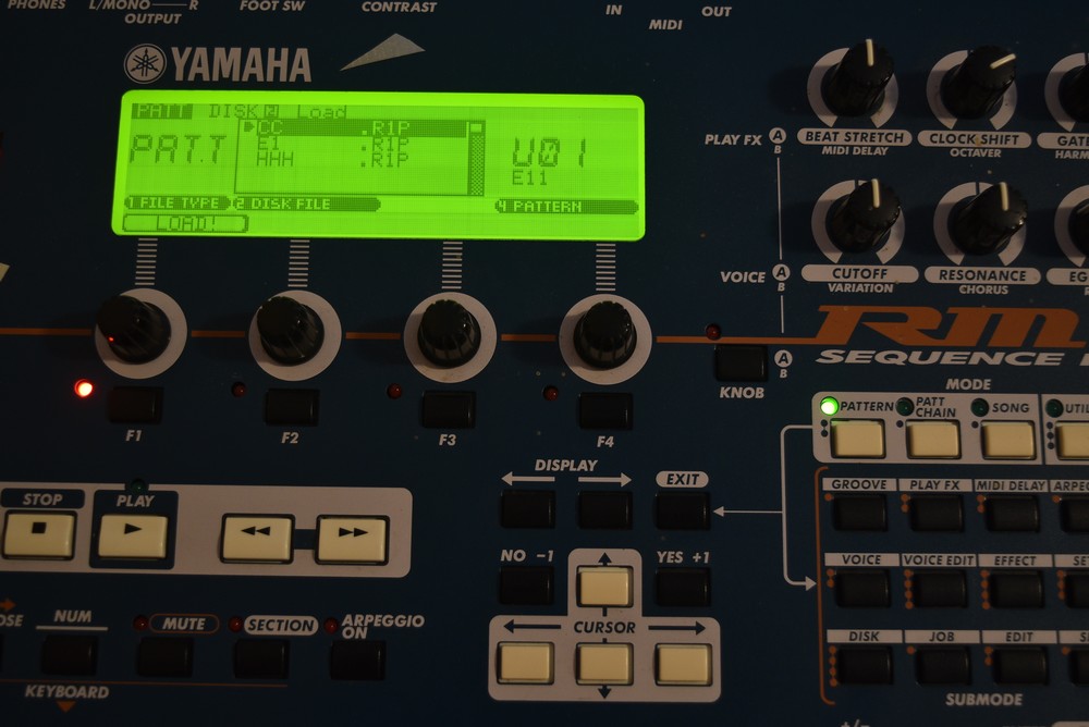
When it's done, it shows the contents of virtual floppy 000:


You can load one of these files into your empty user patch, select the target patch with the 4th knob, it's set to U01 now.  The first virtual floppy is now current and you can load and save to it.  To switch to another floppy, push the right button on the drive once to increment the right digit.  If you press it too many times, keep pressing the right button and it loops around after 9 to 0.  The left button does the same for the tens digit and if you press both buttons it changes the hundreds digit.  When you have virtual floppy 1 selected it will look like this:


Now the file listing is out of date, it still thinks 000 is in the drive.  Do the DISK > F4 > F1 sequence to make it refresh the directory, it will show 'executing' when it reads the new directory:


Hit DISK again to load a file from 001, now the file list is updated and you can use the second virtual floppy.

It's a bit more awkward than just using the buttons on the USB emulator, but it's based on how Yamaha designed the floppy disk interface.  Given the other options, it's a pretty good solution to transfer files to a PC without having to modify firmware on the unit.


SPACE AGE * HI-BOOSTER * TREBLE BOOST PEDAL

Sunday, September 18, 2016

Tuesday, January 20, 2015

DOD FX 25 envelope filter lowpass filter modification

This is a fairly straightforward modification to change the DOD FX25 factory bandpass filter function into either just a lowpass filter or a switchable bandpass/lowpass function.  It really brings a lot of functionality by letting the low end come through the pedal, you can now use the same pedal for guitar OR bass equally.  This is just a mod for the filter section, the other modifications that most people do is on the envelope detector, which I am going to leave factory at this point, IMO it does what it does well enough to leave alone, YMMV though.  This pedal is somewhat infamous from some high profile users: Flea from RHCP and Bill Laswell, the NYC master producer and dub bass legend.

The filter section is based largely on the National Instruments LM13600 datasheet, Figure 14, voltage controlled state variable filter:
In the DOD implementation of the circuit they only brought out the bandpass filter to the outside world, the lowpass filter output has always been in there but was unused in the factory circuit design.  The modification simply changes the default connection between the pedal output circuit and the filter to one or both of the available filter outputs. The pedal I have is what I'll call 'Rev G', two knob with green sparkle paint and gray silkscreen on the top.  There are several different versions of this pedal that have slight differences, they all work in a similar manner so this mod is applicable to any of them.  It seems like the rev G version had higher production numbers and is more common than the rest?  Here is the schematic I am using with the mod on it:


You can also add a switch to select between the two filter outputs, using a SPDT switch.  Wire the center lug to the output capacitor and the two end lugs to the bandpass and lowpass filter output points.  The pedal shell is relatively cramped so I opted to use the lowpass output only and not try to stuff an additional switch into the pedal.  If you wanted to have an indicator for the filter you could use a bi-color LED and a DPDT switch to change LED colors when you switch filter outputs.  Here is the board pic _after_ modification:


One wire was added, so it really is a simple mod to do.  Also note the rev G silkscreen and the opamp socket added to U1.  Sockets are a great thing to add once you have the pedal opened, it allows you to swap out opamps to experiment with different tonal colors.  In this pedal there is only one opamp so it was also a simple mod to do, only half of the opamp handles the audio signal, the other half is for the envelope.  In the pic I'm using a rare, vintage early 80s Japanese made 6458D dual opamp, a relative of the commonly used 4558, a staple in the guitar pedal world.  These are a bit thicker, richer and darker than the stock opamp, in this pedal a later production 1458 from the 90s.  Here are some closeups of the connections:

 For the output connection I de-soldered the near leg of the capacitor C7 and bent it upwards so it was parallel with the board and floated off of it a little bit.  Butt solder a wire to the exposed lead to make the connection.  If you want you can add a dab of superglue to keep the wire held down, I used a solid core wire so it stayed in place fairly well.

For the input connection I was able to sneak the end of the wire under the resistor lead between the resistor body and the hole where it goes into the PCB.  It's a single sided board so there is no via to connect to, doing the connection this way is a bit tricky but you don't have to run a wire all the way to the bottom side of the PCB.

Wednesday, December 10, 2014

modular synthesizer driving cymatic waveform visualizer (experiments)

here's a short clip of some cymatics experiments driven from my modular synthesizer, the audio path is 1 VCO modulated by an LFO into a modulated resonant lowpass filter.  there seems to be a low-level intensity threshold of motion on the surface and also it only seems to respond well to low frequencies, even the midrange doesn't produce much wave motion on the surface....experiments continue...


Thursday, February 16, 2012

Optical Theremin

this is an optically controlled theremin design, the oscillator is a CMOS ring oscillator and the VCA is a 2 transistor circuit based on a roland drum machine. the first half of the demo clip is dry and the second half has digital delay added. my nickname for this one is 'pink percent' because of the way the vinyl records ended up on the front...


Wednesday, February 15, 2012

dual sawtooth oscillator noise synth


this synth is formed from 2 sawtooth oscillators, the first has just a pitch knob and the second one has switchable potentiometer or optical pitch control. there is a switchable cross-modulation control that can be varied to produce different types of sync or ringmodulator effects. both oscillators are mixed together with a blend/crossfade pot and the output section has a gate button and gate mode switch that go to the final master volume control.


atari punk console >> deluxe version


this is a modded version of forrest mims iii's stepped sound generator / atari punk console. this one has switchable potentiometer control or optical control of both the frequency and step knobs. it also has an amplitude modulation section with internal LFO, and the input to this section is switchable between the internal APC output or the input from an external signal...


Thursday, March 24, 2011

Infinity feedback looper

This is the first of my 'SPACE AGE' pedals, it's a single FX chain switcher with footswitchable internal electronic feedback loop.It can be used for 3 purposes: 1. to switch out a single effect or entire effects chain in a true, hardwire bypass, 2. to use internally applied feedback to create lots of interesting new sounds - create oscillators out of distortion boxes, increase the amount of regeneration on delays and chorus/flange type effects and 3. the 'extra' feature is that it can be used as an A/B or A+B box, which either switches between two outputs or adds a second output without shutting off the first one. This can be used to switch between two different amps, or if you have a Fender style two channel amp you can use it to channel switch or add a boost by switching on the second channel. This is a new implementation of the old 'two channel jumper' trick that has been used for a long time, but it's footswitchable which is a nice plus. The circuit is all passive so no batteries are needed, the only downside is there are no status LEDs so you have to tell by ear which mode you are in, which is usually easy to tell if you have the feedback switch on :)

Velvet performance oscillator


This is a sort of a rewind for me back to doing free electronics/oscillators/art synths, this one is a single square wave oscillator with a few features to make it work well as a performance synth. On the top face is a pitch knob and a slide switch to select between the two gate modes: oscillator on/gate to mute or oscillator off/gate to turn on. This is the gate method i used on an earlier oscillator box that i did in 2008, it's a pretty useful combination because it gives you both a constant tone without having to be touching the box (e.g. tweaking other knobs) or to use the oscillator as an accent/splash/rhythmic tone in the normally off position. The slide switch on top also switches between two points in the oscillator circuit, the square wave output and a slightly triangular waveform. On the right side are two buttons, the gate and a tonal shift momentary button that softens up the tone a bit. On the opposite side is the 1/4" output jack that also switches the unit off when the jack is removed. The physical layout is set up so that you can hold it in your left hand, the cable exits above your thumb, and your left index and middle fingers hit the two side buttons. The pitch knob and gate mode switch can be manipulated with your right hand or if you're tricky you can also work the pitch knob with your left thumb. The box is a copper plated project box, the stripes are adhesive backed black velvet which gives a nice visual accent and also gives a really nice tactile feeling. The oscillator circuit is an opamp based square wave with the second half of a dual opamp configured as a follower to buffer the second waveform output. This was a lot of fun to put together and even more fun to jam on, the high frequency oscillations have a really nice warble/pitch fluctuation and the low end square waves have a nice sharp edge to them. This was basically a one-off but I'm thinking about making more similar to this soon...